📣 Firmware Update Release:
Firmware Version v0.23 is now released! Please follow the link here or update via Cloudloop Device Manager.
Installation
RockBLOCK PRO
Before you commence installation of RockBLOCK PRO please ensure that you have considered the following items.
- You have read and fully understood the provided instruction material
- You have a physical installation plan for the Device and Antenna (if installing the PRO-SMA).
- With the appropriate connections to power and any equipment that you wish to connect to the device
- Ensuring that the available antenna cable length is properly considered
- You have all the required additional equipment needed. Including:
- An appropriate power supply unit
- An SMA male 50 Ohm RF terminator if the device is to be used in testing without a connected antenna
- An appropriate antenna mounting solution
- You have a clear end to end service design with the appropriate land network connections in place
Power Connection Options
RockBLOCK PRO can be powered by a conventional DC supply (5-30VDC) or via USB-C. The supply should be capable of delivering 3W to be able to provide sufficient power during peak draw (Iridium transmit and start up).

12-way connector pin assignments for PRO-ANT and PRO-SMA
| Pin | Colour | RS232 (Recommended) | RS4XX/RS422 full duplex | RS4XX/RS485 half duplex (two wire not currently supported) |
|---|---|---|---|---|
| 1 | White | Sleep (Pull to PWR- to activate sleep) * | - | - |
| 2 | Brown | RS232 TX | Serial RS4XX TX (inverting) | ⇄ TX/RX (inverting) |
| 3 | Green | RS232 CTS | Serial RS4XX RX (inverting) | Not connected |
| 4 | Yellow | IO 4 | - | - |
| 5 | Grey | IO 3 | - | - |
| 6 | Pink | IO 2 | - | - |
| 7 | Blue | IO 1 | - | - |
| 8 | Red | PWR+ | - | - |
| 9 | Black | PWR- | - | - |
| 10 | Violet | 0V - REF for IO and serial | - | - |
| 11 | Grey/Pink | RS232 RX | Serial RS4XX RX (non-inverting) | Not connected |
| 12 | Red/Blue | RS232 RTS | Serial RS4XX TX (non-inverting) | ⇄ TX/RX (non-inverting) |
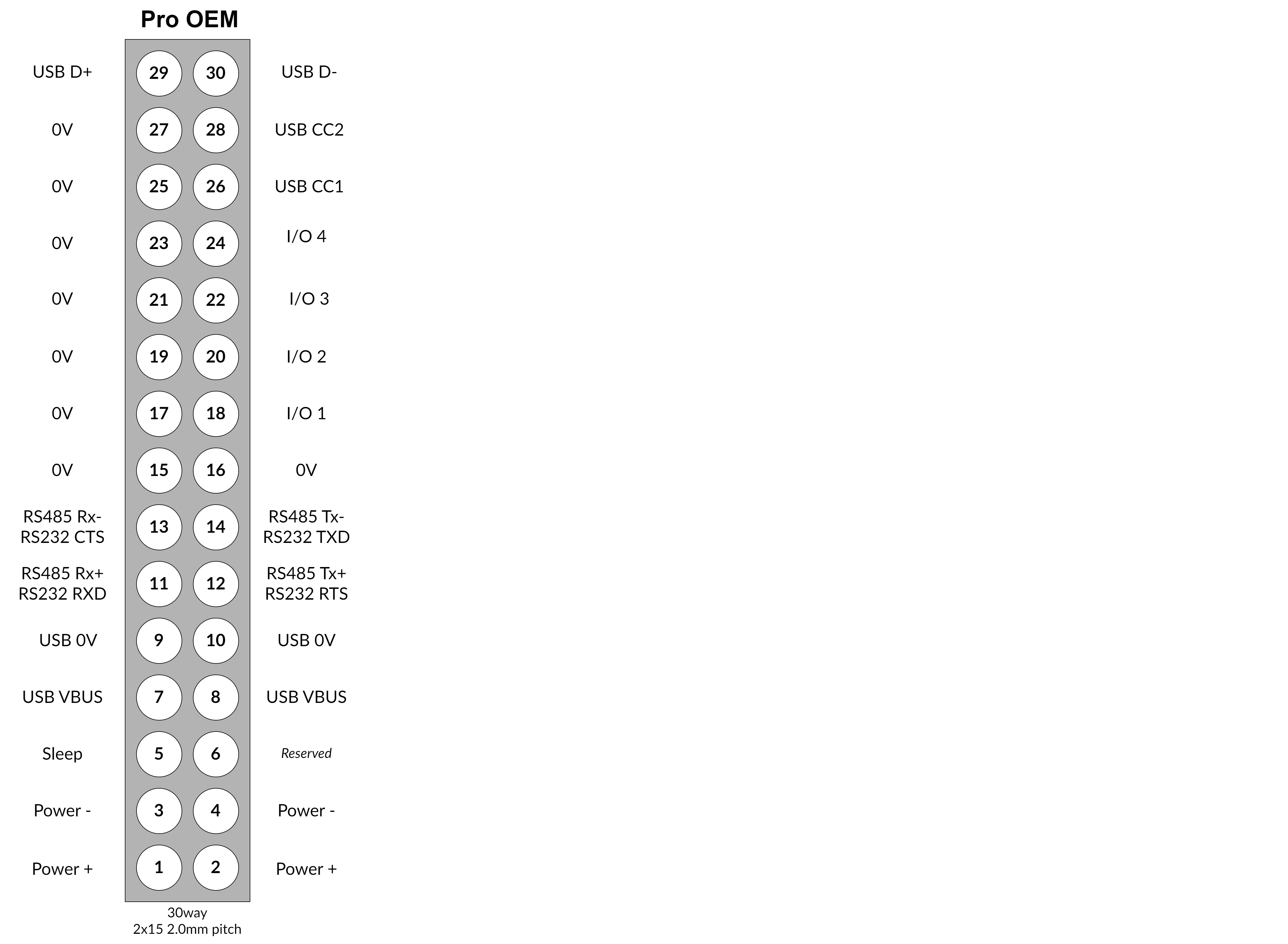
30-way connector pin assignments for PRO-OEM
Detailed installation guidelines for the PRO-OEM can be found HERE
e-SIM
The 9704 modem used inside RockBLOCK PRO is supplied with an e-SIM already installed.
Factory Reset Procedure
Ensure the RockBLOCK PRO is disconnected from power before removing the end panel.
- Unscrew the 4 screws on the plain (or antenna) end panel (the panel without connectors) using a 2.5mm socket head screwdriver.
- The gasket should be retained in the end panel. Take care not to remove or stretch the gasket and keep it free from contamination.
- Locate the RESET button on the left edge of the PCB.
- Hold the RESET button whilst powering on the PRO.
This causes the User Configuration settings to be returned to default.
Mounting RockBLOCK PRO
RockBLOCK PRO is IP66 ingress rated. This means it is suitable for permanent mounting in outdoor locations.
The RockBLOCK PRO installation height should not exceed 2m.
RockBLOCK PRO should be mechanically fastened to a bulkhead or pole using the mounting holes provided. The mounting feet are dual purpose - they have holes for screw mounting or can accept band clamps.
Connecting The Antenna's and Power cables
Step 1a - Connect the Iridium Antenna Cable
Ensure that the Antenna cable is securely connected using the provided Connector.
Customer provided cables should have IP67 rated SMA plugs.
In marine applications, additional protection should be provided to the metallic surfaces by wrapping with amalgamating tape.
Note that in order to comply with the Iridium certification the antenna must be mounted at least 1 metre above the ground or at least 1 metre above any metallic surface that could act as a ground plane.
If the device is being set up prior to installation it is recommended that a 50 Ohm RF terminator is attached to the Iridium antenna connector prior to the device being powered.
Step 2 - Connect the 12 way combined power and serial cable
Insert the power/serial connector into the 12 way port on the device and then switch on the power.
Step 3 - Powering Up
Normal start: Sounds a sequence of notes.
The RockBLOCK PRO does NOT have any external LED indication.
Connectors and cable assemblies
Power and Serial IO 12-pin
| Connector | Manufacturer | Part Number |
|---|---|---|
| Cable assembly - 5m length | Amphenol LTW | M12A-12BFFM-SL8D05 |
USB-C
| Connector | Manufacturer | Part Number |
|---|---|---|
| Cable assembly - 2m length | GTC | GT21C320-01-02 (to USB-C) |
| Cable assembly - 2m length | GTC | GT21C320-04-02 (to USB-A) |