📣 Firmware Update Release:
Firmware Version v0.22 is now released! Please follow the link here or update via Cloudloop Device Manager.
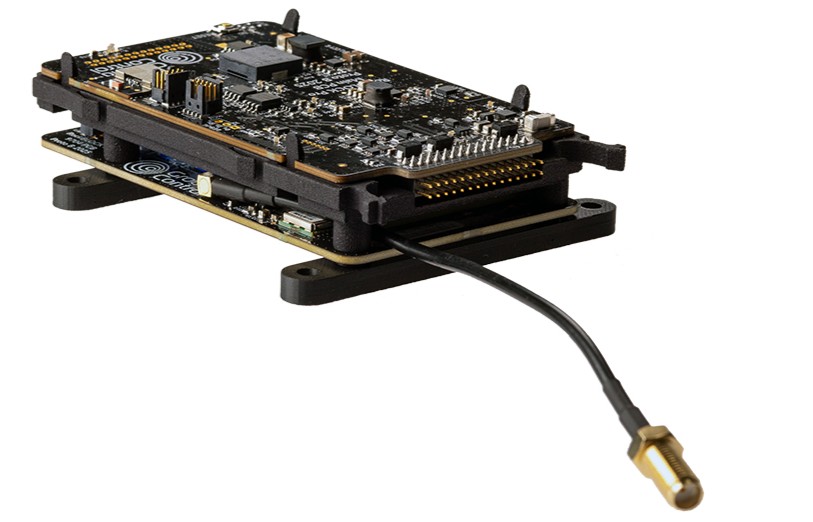
RockBLOCK Pro OEM
RockBLOCK Pro OEM can meet the needs of Iridium certification when all our integration and antenna guidelines are followed. The solution design will also need to be reviewed by the Ground Control team.
Optimised for low power consumption for a market-leading implementation of the Iridium 9704 module.
All essential non-RF connections are made using a single 30way 2x15 2.0mm pitch header.
Designed for easy installation using just 4 screw mounts. (4.2mm holes at 70 x 72mm centres)
Detailed specification and CAD drawings can be found HERE
When powering the unit without an Iridium antenna connected it is important to terminate the RF connection with an RF load to reduce the risk of failure in the 9704 modem RF amplifier stage.
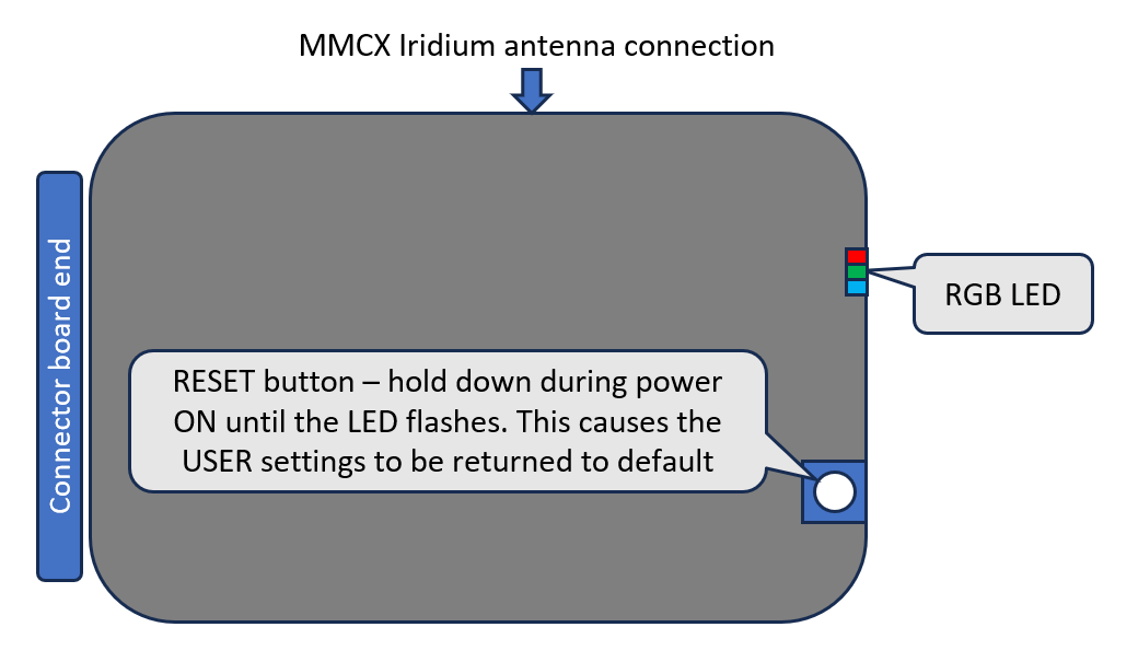
LED indication
| LED colour | Meaning |
|---|---|
| Green (solid) | Powered |
| Green/Red (alternating) | Internal data/File transfer |
| Red (solid) | Fault |
| Blue (solid) | Iridium connection |
| Blue/Green (alternating) | Looking for iridium connection |
Pinout
For orientation of the connector pins the location of pin's 1,2 and 29,30 are marked in the silkscreen of the board.
The part number of the header fitted to the PCBA is Molex 877603016
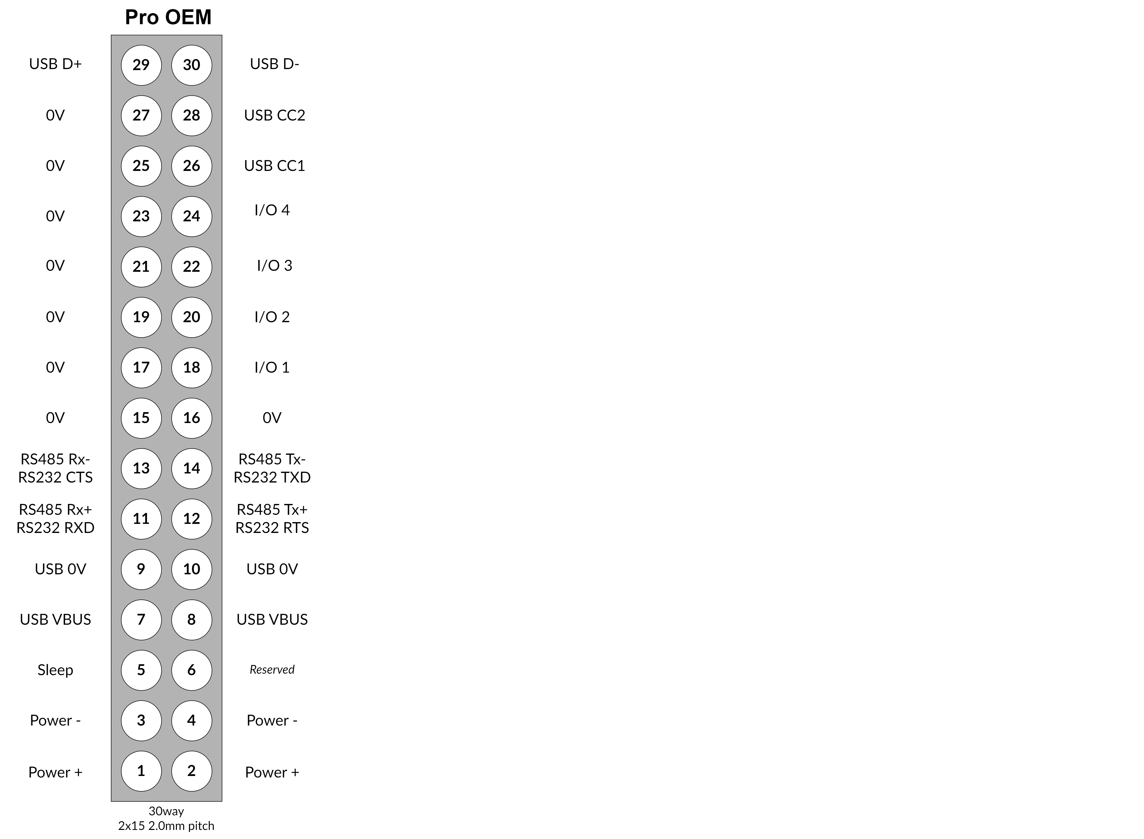 NOTE: This pinout is DIFFERENT from the Mini OEM
Board level user interface
PRO-OEM Integration Guide
The PRO-OEM module is supplied WITHOUT any form of compliance or listing. It is the sole responsibility of the OEM equipment manufacturer to ensure compliance.
In relation to Iridium compliance the OEM equipment manufacturer will need to provide details of the surrounding interfaces, antenna and power supply provisioning to Ground Control Technologies. Our team will check these details to ensure the essential requirements of Iridium certification are met.
The PRO-OEM module provides a similar feature set to the other PRO models. It runs the same firmware and device management via CloudLoop is identical.
This guide will assist you in designing the mechanical and electrical interfaces that are required to support this module within your equipment. A CAD model and 2D drawing are provided in the downloads section below.
Antenna and RF cable
One of the most important design considerations is the selection of antenna type and position. Detailed information regarding antenna selection can be found HERE
Power supply considerations
During Iridium transmit the current draw can reach some significant peaks (see specification below). It is important that the power supply is suitably rated and that the impedance of power supply wiring is low enough to prevent voltage dips below the minimum supply voltage.
Location within your equipment
Chose a location that will provide adequate physical access to the reset button.
Ensure adequate ventilation around the PRO-OEM assembly.
In order to allow use of the BLE features (planned additional config option) a non-conducting aperture should be allowed for in the OEM equipment design in order to allow RF connectivity. As a guide this aperture should be at least 60mm x 60mm.
Mechanical interface
Detailed specification and CAD drawings can be found HERE
The OEM assembly will need to be supported by robust screw fixing at each of the 4 location points. (See GA drawing for dimensions of hole centres.)
The OEM assembly should be protected from excessive shock and vibration.
The MMCX interface to the modem is not designed to withstand forces from cable weight or excessive bending of the cable. It is recommended that additional support is provided directly at the connector. This may take the form of a clamp or some form of non-slump adhesive.
The 30way connector should not be used to provide all the support for any interface PCBA's designed for the OEM application. Additional mechanical fixings should always be provided.
Interfacing to the 30 way connector
All essential non-RF connections are made using the single 30way 2x15 2.0mm pitch header.
When powering the unit without an Iridium antenna connected it is important to terminate the RF connection with an RF load to reduce the risk of failure in the 9770 modem RF amplifier stage. A suitable load is 202117 from Amphenol.
Note:
- Power- and 0V are NOT directly connected. There are filter components between Power- and 0V. 0V is only intended as a reference for comms and I/O
- RS232 is at full drive level. (The circuit makes use of a MAX3160EEAP+ transciever)
- The Sleep pin is an active low input. Pull to 0V to put the PRO-OEM to sleep (if configured to do so).
- I/O digital outputs will be open collector. (Currently not implemented in hardware)
- Chassis GND is related to the Ethernet RJ45 for connection when metal RJ45 plugs and shielded cable are used. It is connected to 0V through a high-impedance.
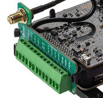
OEM developer board
In order for customers to trial the PRO-OEM functionality and to provide a reference design we are able to provide the OEM interface PCBA pictured below. This gives access to all functions brought out on the 30 pin header including USB-C This board also includes a position for mounting an SMA connector.
Note the required orientation of the interface board with the terminals along the upper edge. Inverting the board on the 30 way header WILL DAMAGE the OEM board. See image below.
| OEM connector PCB - Interface for developers | WARNING! Interface board orientation must be as shown below |
|---|---|
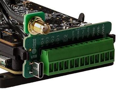 |  |