Hardware
Dimensions
RockBLOCK 9604 Dimensions
WIP
CAD data is available to download at the bottom of the page.
Initial Connection
DC Input
The red 'PWR' LED should illuminate, and the supercapacitors will begin charging. With the default current limit, this can take around 40 seconds. The 9604 module will start up, and the Green 'RDY' LED should illuminate.
Battery Input
The red LED will not illuminate.
USB Input
The red 'PWR' LED should illuminate, and the supercapacitors will begin charging. With the default current limit, this can take around 40 seconds. The 9604 module will start up, and the Green 'RDY' LED should illuminate.
If using USB, the RockBLOCK 9604 should be plugged directly into a USB 2.0 or USB 3.X port, which must be able to supply 500mA. For this reason, the use of unpowered USB hubs is not supported.
Communication
RockBLOCK 9604 has a USB-TTL Type-C interface for quick and easy communication, or a 26-pin 0.1" pitch interface for full control and the highest efficiency capability.
The USB-TTL interface and the 26-pin connector share a serial interface on the 9604.
Simultaneous connection of both interfaces may cause damage to the RockBLOCK 9604.
Using USB Type-C:
There are two USB-C ports.
- J5 provides Tx and Rx comms with the 9604.
- J6 Reserved for future use.
Startup Sequence
- Connect a USB-Type C cable from the RockBLOCK 9604 to a USB port on end device.
- The RockBLOCK 9604 will get powered from the USB interface.
- The USB port will enumerate on the end device once the 9604 has booted successfully.
Shutdown Sequence
- Unplug / power down the USB port
- The module will automatically shut down on capacitor power.
Connections
RockBLOCK 9604 Connector Pinout
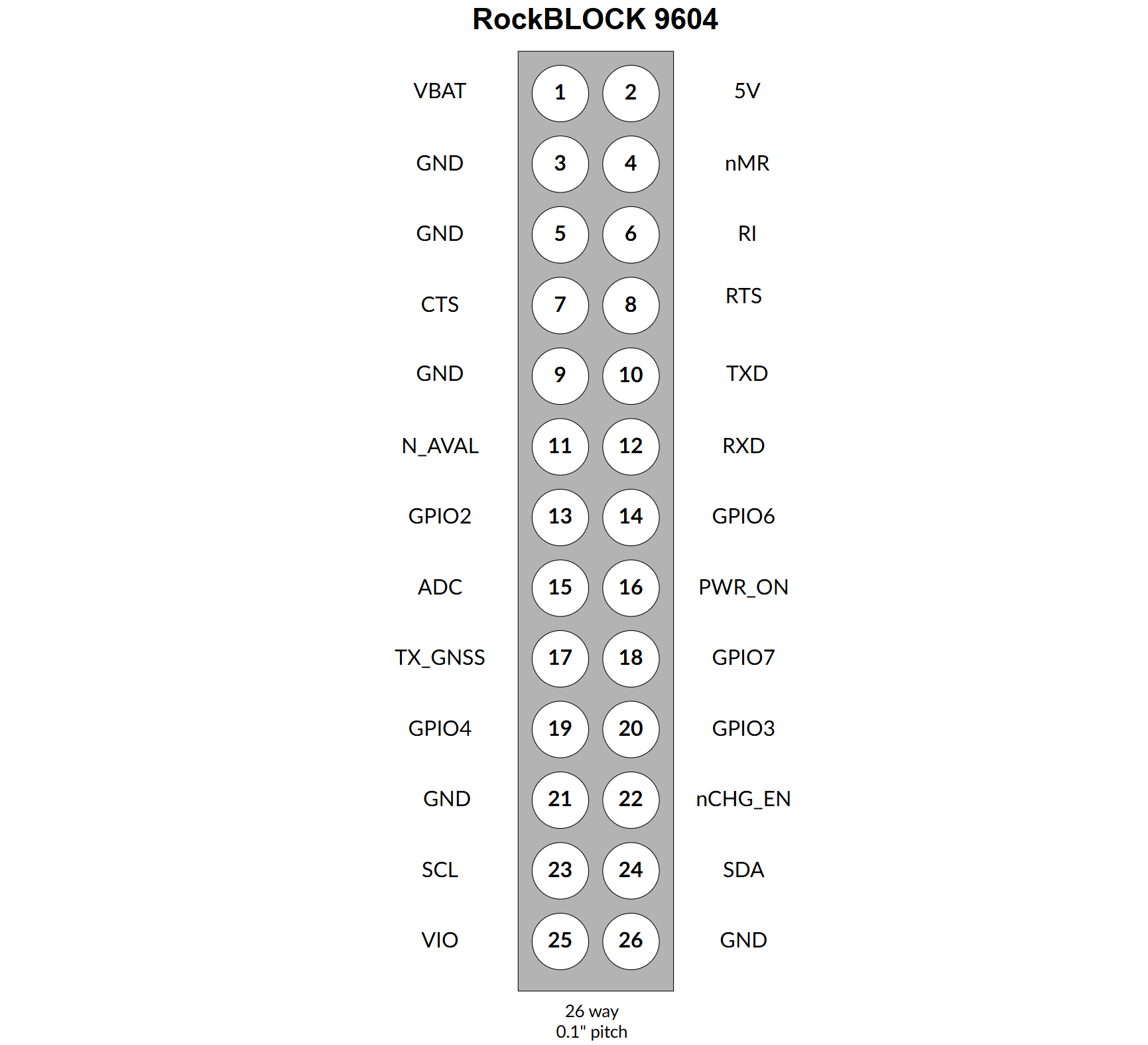
| Pin | Label | Function | Type | Direction |
|---|---|---|---|---|
| 1 | VBAT | Allows the 9604 module to be powered directly from an external Li battery. V range 3.3 to 4.2V | Power | IN |
| 2 | 5V | External supply option. Range 3.6 - 5V (450mA limit) | Power | IN |
| 3 | GND | Power Ground | GND | GND |
| 4 | nMR | Drive low to hold the 9604 in reset. | Logic | IN |
| 5 | GND | Power Ground | GND | GND |
| 6 | RI | Ring Indicator signal (ACTIVE LOW) | Logic | OUT |
| 7 | CTS | Iridium 9604 CTS (output from RockBLOCK) | Logic | OUT |
| 8 | RTS | Iridium 9604 RTS (input to RockBLOCK) | Logic | IN |
| 9 | GND | Signal Ground | GND | GND |
| 10 | TXD | Serial TXD - 3V3 level (input to RockBLOCK) | Logic | IN |
| 11 | N_AVAIL | Iridium Network Indicator | Logic | OUT |
| 12 | RXD | Serial RXD - 3V3 level (output from RockBLOCK) | Logic | OUT |
| 13 | GPIO2 | Pin with alternatively configurable functions. | Logic | IN/OUT |
| 14 | GPIO6 | Pin with alternatively configurable functions. | Logic | IN/OUT |
| 15 | ADC_IN | ADC input. Level can be read by AT command. | Analogue | IN |
| 16 | PWR_ON_IN | Drive high to power the 9604 OFF. | Logic | IN |
| 17 | TXD_GNSS | GNSS UART data output from internal u-blox M10 chip. - 3V3 level | Logic | OUT |
| 18 | GPIO7 | Pin with alternatively configurable functions. | Logic | IN/OUT |
| 19 | GPIO4 | Pin with alternatively configurable functions. | Logic | IN/OUT |
| 20 | GPIO3 | Pin with alternatively configurable functions. | Logic | IN/OUT |
| 21 | GND | Signal Ground | GND | GND |
| 22 | nCHG_EN | Turn off charging of super capacitors when using VBAT_IN | Logic | IN |
| 23 | SCL | 9604 I2C Host Clock - 3V3 level | Logic | OUT |
| 24 | SDA | 9604 I2C Host Data - 3V3 level | Logic | - |
| 25 | VIO | Option to power the internal level translator. Requires Removal of R3 and fit R63 OR (0402) | Logic | IN |
| 26 | GND | Signal Ground | GND | GND |
LED Indicators
| Label | Colour | Indication |
|---|---|---|
| PWR | Red | input voltage is present (Does not illuminate when battery powered) |
| 9604_RDY | Green | 9604 Module is powered and booted |
| GPIO2 | Green | Status of GPIO2 |
| GPIO3 | Green | Status of GPIO2 |
| GPIO4 | Green | Status of GPIO2 |
| GPIO6 | Green | Status of GPIO2 |
| GPIO7 | Green | Status of GPIO2 |
Downloads
Schematic
CAD data
These documents are intended to provide early access information to interested parties during the development process. Whilst we strive to maintain accuracy, any part of the specification or design of these products may change without notice.
These documents were last reviewed for accuracy on October 12th 2026.