Antenna Options
9704 Modem Output characteristics
| Parameter | Value |
|---|---|
| Frequency Range | 1616 MHz to 1626.5 MHz |
| Input / Output Impedance | 50 Ω |
| Average RF power (Conducted i.e. measured at the RF connector) | +32 dBm (1.58W) |
| Peak RF power (Conducted i.e. measured at the RF connector) | +37 dBm (5W) |
In order to comply with the Iridium certification the antenna must:
- be mounted at least 1 metre above the ground or at least 1 metre above any metallic surface that could act as a ground plane.
- have a clear view of the sky.
- be mounted so that the axis of the antenna is pointing vertically upwards.
RockBLOCK 9704-SMA
For each antenna option, the total loss presented by cables and connectors used between the 9704 and antenna must be within the Minimum and Maximum cable loss ranges specified below in order to meet Iridium certification requirements.
The options shown in the table below are based on the following cable and connector loss assumptions for the Iridium 9704 operating frequency range:
LMR240 loss 0.34dB/m
0.1dB per connector.
This page is intended only to act as a guide. Installers are advised to carry out their own calculation and measurement of loss for any RF cable assembly used. 9704 IMT services operate between 1616MHz - 1626.5MHz.
Outside enclosures connectors should have at least an IP66 ingress rating.
In all cases the antenna should be installed pointing vertically at the sky.
9704-SMA Qualified Antenna
| Ground Control Part Number | MFT Part Number | Gain | Antenna end Connector | Cable | Min loss | Max loss |
|---|---|---|---|---|---|---|
| ACC-HELANT-9704 | Maxtena 100-00003-02 | 2.8 dBic (typical) | SMA socket - SMA socket bulkhead adaptor (e.g RS 246-9405) | LMR240 SMA plug to SMA plug, 1m maximum | 0dB | 0.5dB |
The 9704-SMA can also be used with the antenna mounted directly at the PCB.
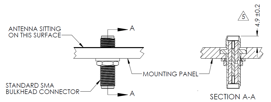
ACC-HELANT-9704 sealing against a bulkhead
The antenna is fitted with an o-ring in the base that acts as a gasket when the antenna is screwed down onto a flat smooth
surface. In order to maintain both a good electrical connection and seal it is important that the dimensions match the drawing
below.