Introducing RockBLOCK Plus 9704
RockBLOCK Plus 9704 takes all the features of RockBLOCK 9704, and adds a fully watertight enclosure, onboard ublox MAX-M10S GNSS, simplified IO, wide operating voltages for power and control, and dual RS-232 ports for Iridium and GNSS.
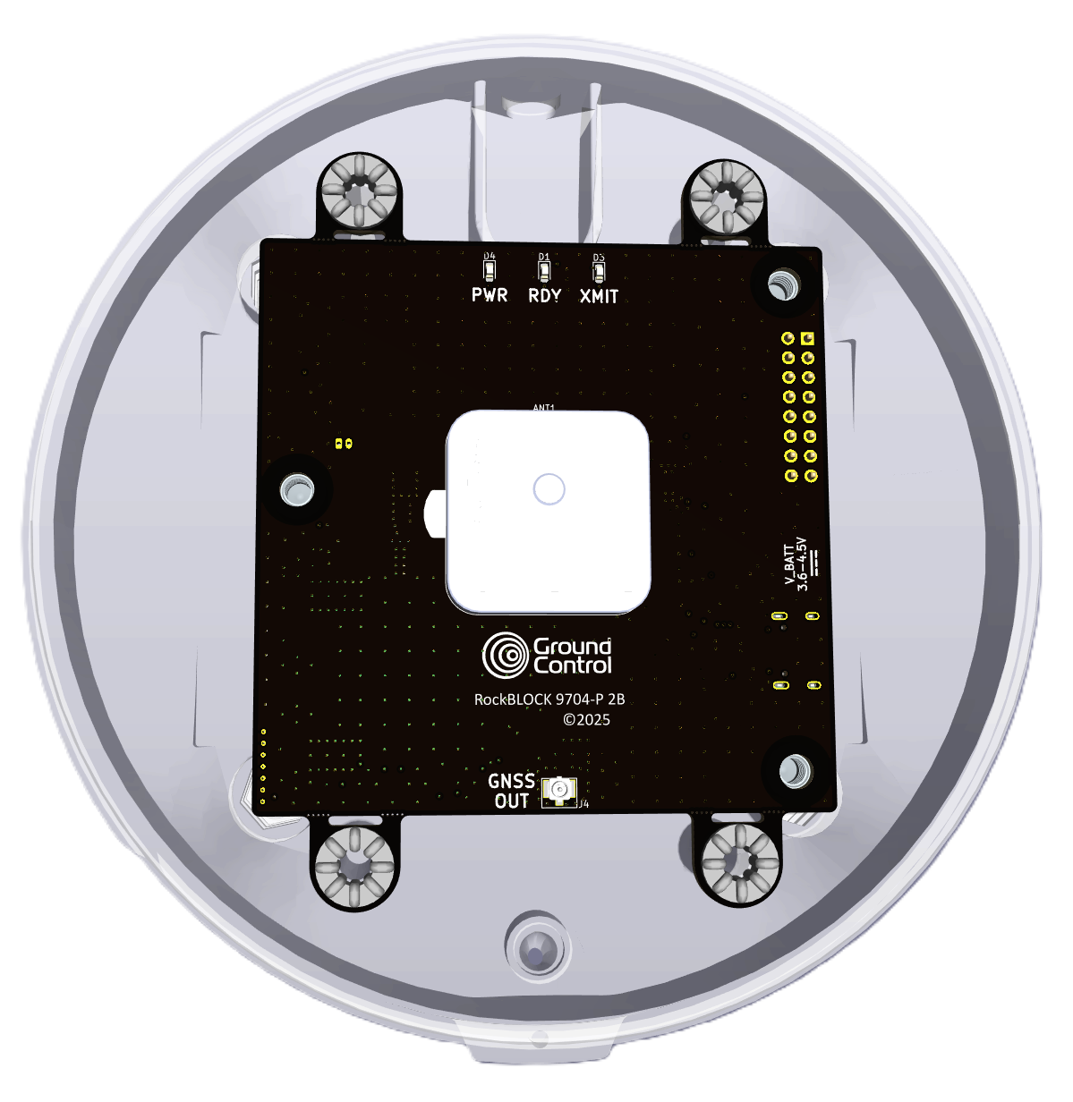
Open case top view - RockBLOCK 9704-ANT mounted in a weatherproof enclosure
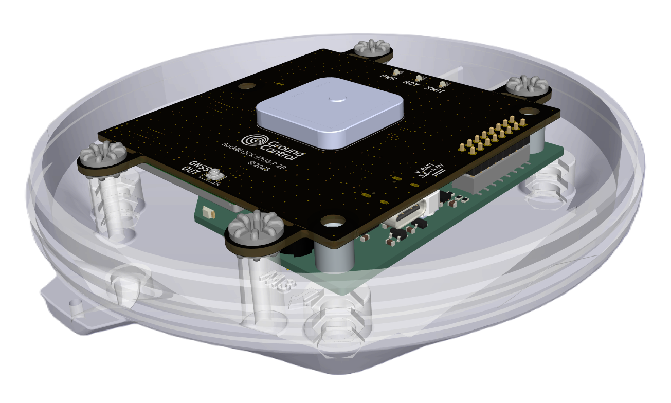
Open case 3-Quarter top view
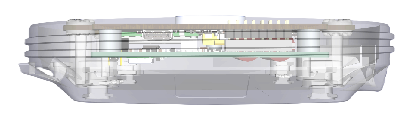
Through case side view
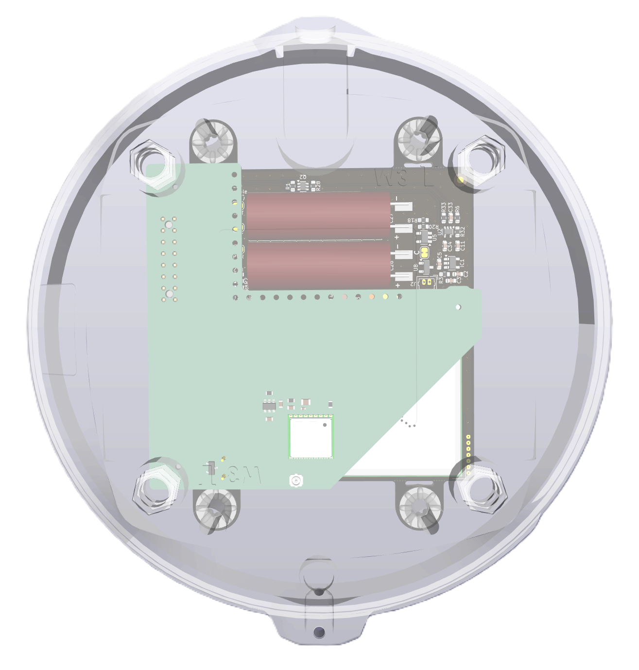
Through case 3-Quarter bottom view
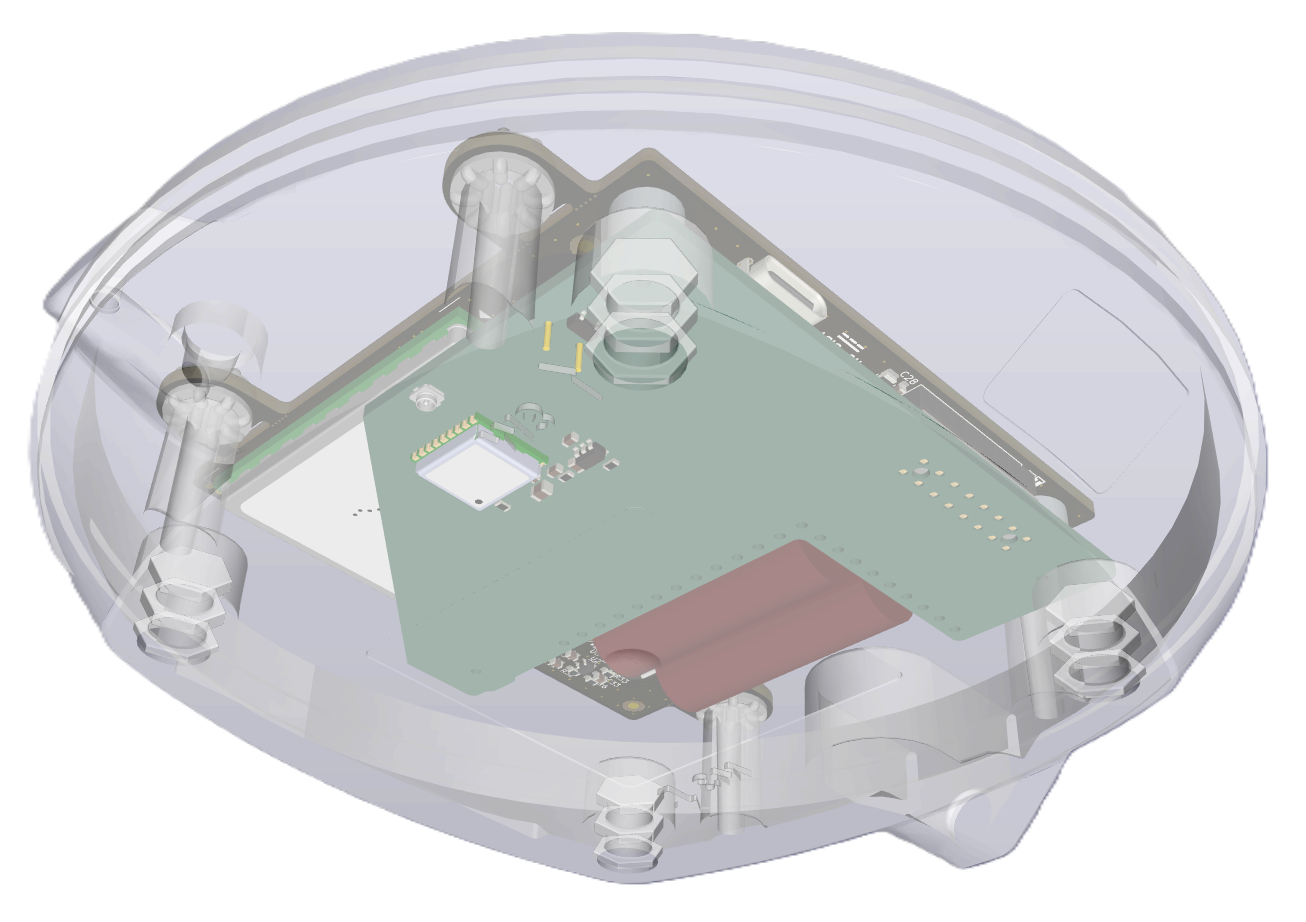
Through case bottom view - RockBLOCK 9704-ANT addon board carrying Power Supplies, Transceivers, and GNSS
Electrical
Indicative maximum power consumption values only. See detailed power figures further down the page.
| Voltage | 7.0 - 30.0V DC |
| Power consumption (Transmitting) | < 2.0W |
| Power consumption (Inrush Limit) | < 6.7W |
| Cable Connections | 8-core 0.25mm2 cable. 3m, 5m, 10m and 15m lengths available. |
Communication
RockBLOCK Plus 9704 has two RS-232 ports. The default baud rate of the GNSS device can be changed if desired.
| Setting | 9704 | GNSS |
|---|---|---|
| Baud | 230400 | 9600 |
| Data Bits | 8 | 8 |
| Parity | None | None |
| Stop Bits | 1 | 1 |
Signal Thresholds
The host device should be compatible with the following I/O voltages to ensure trouble-free operation of the RockBLOCK Plus 9704
| RockBLOCK Plus 9704 Pin | V Min. | V Max. | I Max. (mA) |
|---|---|---|---|
| DC Power | 7.0 | 30.0 | 1000 |
| Logic In LOW | 0.0 | 0.4 | -0.3 |
| Logic In HIGH | 2.5 | 30.0 | 0.3 |
| RS-232 In LOW | -15.0 | 0.6 | -5 |
| RS-232 In HIGH | 2.4 | 15.0 | 5 |
| RS-232 Out LOW | -5.5 | -5.0 | -30 |
| RS-232 Out HIGH | 5.0 | 5.5 | 30 |
Pinout
| Cable Core | Function | Type | Direction |
|---|---|---|---|
| Black | Ground | GND | GND |
| Red | Positive input voltage | Power | Input |
| Blue | Iridium 9704 RS-232 TX | Data | Output |
| Pink | Iridium 9704 RS-232 RX | Data | Input |
| White | Iridium 9704 Enable | Logic | Input |
| Green | uBlox M10 GNSS RS-232 TX | Data | Output |
| Yellow | uBlox M10 GNSS RS-232 RX | Data | Input |
| Grey | uBlox M10 GNSS Enable | Logic | Input |
Functional Modes
The RockBLOCK Plus 9704 can be used as a standalone ruggedised RockBLOCK 9704, Standalone GNSS, or both together. The table below outlines the functional modes.
| Function | Power In | 9704 Enable | GNSS Enable |
|---|---|---|---|
| Off | LOW | X | X |
| Sleep | > 7.0V | < 0.4V | < 0.4V |
| 9704 Only | > 7.0V | > 2.5V | < 0.4V |
| GNSS Only | > 7.0V | < 0.4V | > 2.5V |
| 9704 & GNSS | > 7.0V | > 2.5V | > 2.5V |
- When both 9704 and Iridium are enabled, during an Iridium transmission the 9704 module will actively gate the internal antenna between 9704 and GNSS. During periods of heavy continuous data transmission, this may cause temporary delays in GNSS position update.
In order to save power, no 'pulls' are implemented on the Enable wires. Whilst the default state of both will be low, it is possible that cable capacitance could lead to unpredictable behaviour if the Enable wires are left to float.
Therefore, it is recommended that the Enable pins are driven by a push-pull driver. In situations where either or both 9704 and GNSS are required to be enabled all the time, the Enable wire(s) can be tied directly to the supply voltage.
If used in a low EMI environment, a user-fitted pulldown, or no pulldown may be completely sufficient.
Power Consumption Data
Indicative power consumption values only. Figures for specific use cases may differ significantly depending on individual device configurations.
| Operating Mode | 9704 Enable | GNSS Enable | Supply Voltage (V) | Average Power (mW) |
|---|---|---|---|---|
| Inrush (RB9704 Capacitor Charging. For first ~30s following power application) | X | X | 7.0 (15m cable) | 6700 |
| 7.0 | 5700 | |||
| 12.0 | 4700 | |||
| 24.0 | 4600 | |||
| Idle | LOW | LOW | 7.0 | 4.9 |
| 12.0 | 4.8 | |||
| 24.0 | 6.0 | |||
| 9704 Off GNSS On | LOW | HIGH | 7.0 | 161 |
| 12.0 | 168 | |||
| 24.0 | 180 | |||
| 9704 Idle GNSS Off | HIGH | LOW | 7.0 | 102 |
| 12.0 | 108 | |||
| 24.0 | 120 | |||
| 9704 Initialised GNSS Off | HIGH | LOW | 7.0 | 119 |
| 12.0 | 120 | |||
| 24.0 | 145 | |||
| 9704 Initialised GNSS 'Aquire' | HIGH | HIGH | 7.0 | 147 |
| 12.0 | 156 | |||
| 24.0 | 168 | |||
| 9704 Initialised GNSS 'Tracking' | HIGH | HIGH | 7.0 | 168 |
| 12.0 | 168 | |||
| 24.0 | 180 |
The above measurements were taken with a 10m cable, unless otherwise noted.
Using RockBLOCK Plus 9704
Powering
When RockBLOCK 9704 is first connected to power, the onbaord capacitors will need to charge before the 9704 is ready to communicate. If the unit has been unpowered for a period of days, this can take up to 40 seconds.
The GNSS module is not subject to the delay requirement, and will be ready to communicate over RS-232 straight away, however it will not be able to start receiving a position until the 9704 capacitors are charged.
Power Supply Protection and Compliance
For compliance purposes, it is mandatory that the device’s power supply is protected by a 1A fuse installed in line with the positive supply.
Communication
RockBLOCK Plus 9704 can be used with the Ground Control RockBLOCK 9704 software libraries. Please follow the instructions for connecting via USB, and select your RS-232 adapter as the serial device.
Communication with the ublox MAX-M10S GNSS is possible using either NMEA (default 4.11) or UBX protocols. Please consult the ublox Interface Manual for full details.
For the purposes of testing, the ublox software u-center 2 can be used to communicate with the onboard GNSS module.
Environmental specification
Operating temperature range -40°C to +70°C (Storage -40°C to +85°C)
RockBLOCK Plus is designed to be permanently installed in hostile environments.
The radome is moulded from ASA, which is inherently UV stable.
RockBLOCK Plus has an IP68 ingress rating, which means it is (at least) sealed against water ingress when submerged for 30 minutes at a depth of 3m.