Key Functionality
Sensing
The RockBLOCK Sense/Switch can automatically transmit a value or a group of values acquired as samples from one or more of the inputs. Values can be transmitted from each of the three configurable digital inputs as well as the analogue input.
📘 Minimum Transmission Frequency
Please note that the minimum time between SBD (Short Burst Data) messages is 15 seconds.
Sampling and Transmission
- Digital Inputs: The device can handle up to three digital inputs.
- Analogue Input: One channel available for analogue input.
- Group Transmission: Higher group transmission values are more efficient on SBD data, reducing airtime costs.
Example Settings
- Channel 0: Sampling every 5s, transmitting in groups of 12.
- Channel 1: Sampling every 10s, transmitting in groups of 6.
- Channel 2: Sampling every 60s, transmitting in groups of 1.
- Channel 3: Sampling every 2s, transmitting in groups of 30.
Value-Based Alerts
Users can configure both upper and lower trip levels on the analogue channel (3). Alerts will be sent if the measured value crosses these levels and stays above or below for the time sensitivity duration.
Configuring Alerts
- Upper Trip: Can be set to any level over the range but not lower than the lower trip. If the upper trip is set to the maximum value, the upper level triggered alert is disabled.
- Lower Trip: Can be set to any level over the range but not higher than the upper trip. If the lower trip is set to the minimum value, the lower level triggered alert is disabled.
- Hysteresis: To prevent multiple triggers around the trip level, users can set a hysteresis value up to a maximum of 1.28V or 2.1mA.
Digital Input Alerts
Alerting is also available on the digital inputs, triggered by positive or negative edge transitions. The time sensitivity rule helps avoid spurious alerts. The function is enabled by selecting the appropriate channel mode when configuring.
Alert Frame Information
When a channel alert is sent, the following information is included:
- Reason: Type of alert (rising edge, falling edge, above upper trip, below lower trip).
- Channel Number: The channel that triggered the alert.
- Mode: The mode the channel was set to.
- Time Stamp: Time when the alert was triggered.
- Channel Value: The value at the point the alert was triggered.
Switching
Channel 2 can be configured as a switch output. The RockBLOCK switch output is achieved by a single mosfet in open drain configuration.
Switch Configuration
- State Definition: When the mosfet is OFF, the state is HIGH (external voltage pull-up). When the mosfet is ON, the state is LOW (current drawn through the load).
Timer Settings
The RB Switch can be set as a timer to produce a single LOW pulse or repeating LOW pulses on a fixed timebase. A single message via the server and Iridium SBD can trigger the action.
Timer Frame Overview
- 2 bytes: Header - Ground Control specific identifier.
- 1 byte: Frame format - Ground Control specific identifier.
- 2 bytes: Reserved for future use.
- 1 byte: Time period (0x01 = 10s, increments of 10s up to 0xff = 42m 30s).
- 1 bit: Single pulse (0) or repeating pulses (1).
- 7 bits: Linear % scale - proportion of the time period the output is switched LOW (0x00 = 0%, 0x7f = 100%).
Example Scenarios
- Landing Lights: Continuous ON until another message is sent.
- Time period: 0xff
- Pulses: Repeat (1)
- Switch %: 0x7f (100%)
- Light Beacon: Blinking pattern (e.g., 10s ON every 30s).
- Time period: 0x03 (30s)
- Pulses: Repeat (1)
- Switch %: 0x2a (33%)
- Remote Reset: Single pulse for a remote system reset (e.g., power off for 10s).
- Time period: 0x01 (10s)
- Pulses: Single (0)
- Switch %: 0x7f (100%)
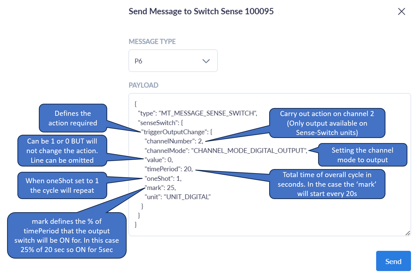
Full breakdown of the options in P6 MT messaging for Sense Switch configuration
Further guidance on setting an output. In this case switching the output MOSFET on channel 2 (Grey wire) on for 5s and repeating this every 20s.