📣 Firmware Update Release:
Firmware Version v0.23 is now released! Please follow the link here or update via Cloudloop Device Manager.
Installation
RockREMOTE Mini
Before you commence installation of RockREMOTE Mini please ensure that you have considered the following items.
- You have read and fully understood the provided instruction material
- You have a physical installation plan for the Device and Antenna
- With the appropriate connections to power and any equipment that you wish to connect to the device
- Ensuring that the available antenna cable length is properly considered
- You have all the required additional equipment needed. Including:
- An appropriate power supply unit
- RJ45 ethernet cable and laptop for device configuration.
- A TNC male 50 Ohm RF terminator if the device is to be used in testing without a connected antenna
- An appropriate antenna mounting solution
- You have a clear end to end service design with the appropriate land network connections in place
Power Connection Options
RockREMOTE Mini can be powered by a conventional DC supply (10-30VDC) or Power over Ethernet+ (PoE+).
The supply should be capable of delivering 25W to be able to provide sufficient power during peak draw (Iridium transmit and start up).

| Pin | Colour | RS232 (Default) | RS4XX full duplex | RS4XX half duplex (See Note) |
|---|---|---|---|---|
| 1 | Brown | Sleep (Pull to PWR- to activate sleep) | - | - |
| 2 | Blue | Serial RS232 RTS | Serial RS4XX TX (non-inverting) | ⇄ TX/RX (non-inverting) |
| 3 | White | Serial RS232 TX | Serial RS4XX TX (inverting) | ⇄ TX/RX (inverting) |
| 4 | Green | Serial RS232 CTS | Serial RS4XX RX (inverting) | Not connected |
| 5 | Yellow | IO 4 | - | - |
| 6 | Gray | IO 3 | - | - |
| 7 | Pink | IO 1 | - | - |
| 8 | Red | PWR+ (10-30VDC) | - | - |
| 9 | Black | PWR- | - | - |
| 10 | Orange | 0V - REF for IO and serial | - | - |
| 11 | Purple | Serial RS232 RX | Serial RS4XX RX(non-inverting) | Not connected |
| 12 | Light Green | IO 2 | - | - |
GPIO IO channels 1-4 are not available on the standard product.
IO Outputs will be Open-Drain. Floating = Float/disconnected. Low = Shorted to 0 V.
IO Inputs will be Active-Low with internal pull-up. High = Float/disconnected. Low = Shorted to 0 V.
RS485 Half Duplex is NOT currently fully supported in firmware.
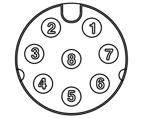
Ethernet pin out
The following reference can be used to fabricate suitable ethernet connector cables directly to the 8 pin circular connector.
| Circular connector Pin | RJ45 plug pin | Function |
|---|---|---|
| 3 | 8 | PoE+ |
| 2 | 7 | PoE+ |
| 8 | 6 | Rx- |
| 5 | 3 | Rx+ |
| 7 | 4 | PoE- |
| 1 | 5 | PoE- |
| 4 | 2 | Tx- |
| 6 | 1 | Tx+ |
Circular connector pin out 'looking into bulkhead mounted receptacle mounted on Mini'
PoE+
Use the 8 way Ethernet connector cable (Amphenol AB-AU08FL-UPBML-QH002 or AB-AU08FL-UPBML-QH005) to connect to a PoE+ enabled switch with the capacity to deliver at least 25W.
When the PoE+ is connected the Red PWR+ wire should be left open circuit and prevented from touching any other connectors.
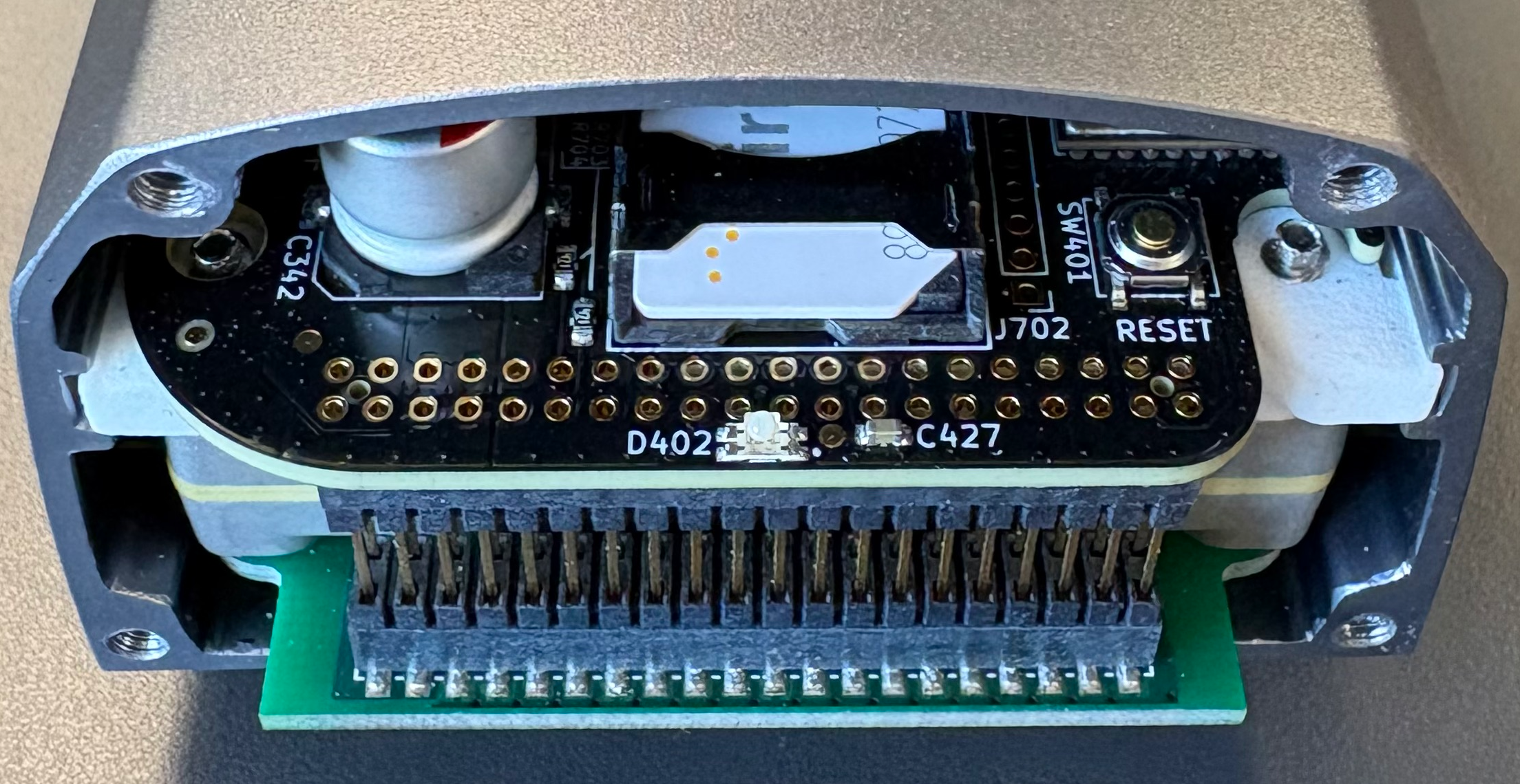
Installing SIM cards
RockREMOTE Mini comes with an Iridium Certus SIM card pre-installed as standard.
Should access be required to remove or install a replacement SIM the following steps should be taken:
- Unscrew the 4 screws on the plain end panel (the panel without connectors) using a 2.5mm socket head screwdriver.
- The gasket should be retained in the end panel. Take care not to remove or stretch the gasket and keep it free from contamination.
- To remove an existing SIM push the stainless steel slide bar back and the hinged carrier will spring up slightly.
- To insert a new SIM, orientate the SIM card correctly and insert it into the carrier. The hinged carrier can then be pushed down and the slide bar pulled back to lock it in place.
- Reassemble the panel. Carefully check the orientation and alignment. Torque the screws to around 0.75Nm
- Only repower the device after full reassembly.
- See diagram below for reference.
RockREMOTE Mini is compatible with mini (2FF) size SIM format.
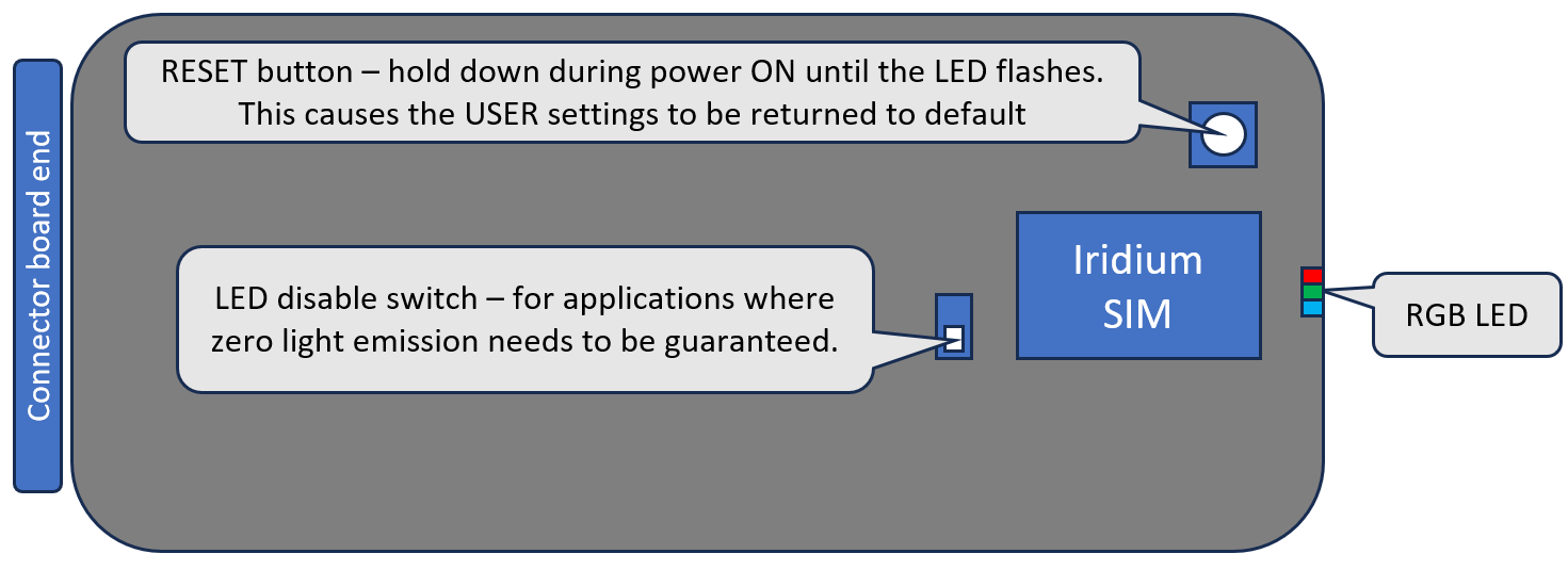
LED indicator - disable option.
There is a small switch located just behind the SIM card that provides a method to completely isolate the LED indicator if the unit needs to be guaranteed to be dark while in operation.
- Follow the instructions above to remote the plain end panel.
- See diagram below for reference.
Location of PCBA buttons
Mounting RockREMOTE Mini
RockREMOTE Mini is IP66 ingress rated. This means it is suitable for permanent mounting in outdoor locations.
RockRemote Mini should be mechanically fastened to a bulkhead or pole using the mounting holes provided. The mounting feet are dual purpose - they have holes for screw mounting or can accept band clamps.
Connecting The Antenna's and Power cables
Step 1a - Connect the Iridium Antenna Cable
Ensure that the Antenna cable is securely connected using the provided Connector.
Customer provided cables should have IP67 rated TNC plugs.
In marine applications, additional protection should be provided to the metallic surfaces by wrapping with amalgamating tape.
Note that in order to comply with the Iridium certification the antenna must be mounted at least 1 metre above the ground or at least 1 metre above any metallic surface that could act as a ground plane.
If the device is being set up prior to installation it is recommended that a 50 Ohm RF terminator is attached to the Iridium antenna connector prior to the device being powered up
Step 1b - Connect the GNSS
Connect the GNSS (L1) if required. Use SMA connectors with the appropriate level of environmental protection.
In marine applications, additional protection should be provided to the metallic surfaces by wrapping with amalgamating tape.
Step 2 - Connect the 12 way combined power and serial cable
Insert the power/serial connector into the 12 way port on the device and then switch on the power.
Step 3 - Powering Up - LED sequence
Normal start: Green flash then solid green. Turns 'pale' greeney-blue when Iridium modem goes active
Connectors and cable assemblies
Ethernet 8-pin
| Connector | Manufacturer | Part Number |
|---|---|---|
| Bulkhead connector | Amphenol LTW | AU-08PMMP-QC800 1 |
| Cable plug connector | Amphenol LTW | AU-08BFFA-QL8AP0 |
| Cable assembly - 2m length | Amphenol LTW | AB-AU08FL-UPBML-QH002 |
Power and Serial IO 12-pin
| Connector | Manufacturer | Part Number |
|---|---|---|
| Bulkhead connector | Amphenol LTW | BU-12PMMP-LC7001 |
| Cable plug connector | Amphenol LTW | BU-12BFFA-LL7001 |
| Cable assembly - 2m length | Amphenol LTW | BU-12BFFM-LL7A02 |