📣 Firmware Update Release:
Firmware Version v0.19 is now released! Please follow the link here or update via Cloudloop Device Manager.
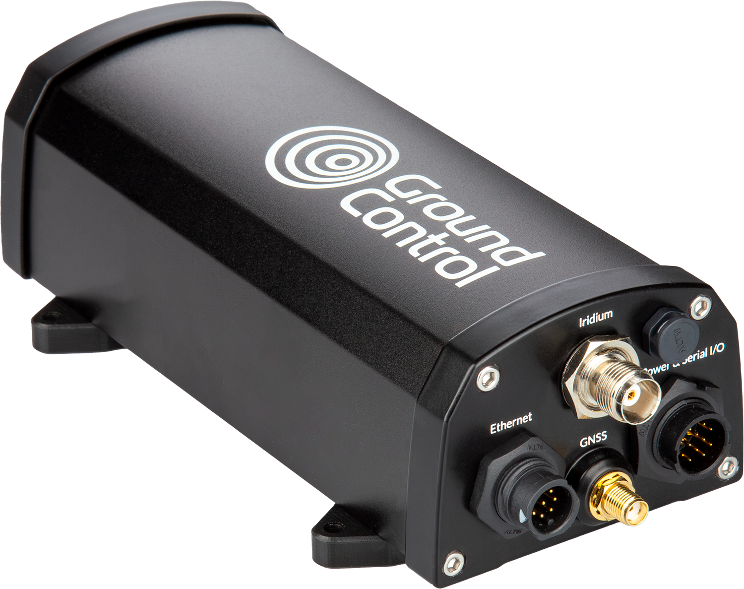
RockREMOTE Mini
We launched RockREMOTE Mini as a ready-to-deploy terminal in June 2024, early customer trials began in April 2024.
Satellite connectivity via the built in Iridium Certus 100 module.
Make TCP/IP connections or use the more efficient IMT messaging protocol from Iridium.
Configuration of ethernet LAN and the WAN will be accomplished via Bluetooth (BLE) using a companion App or API.
RockREMOTE Mini is optimised for low power consumption for a market-leading implementation of the Iridium Certus 100 module.
The unit can also be supplied by Power Over Ethernet Plus (POE+).
 |  |
|---|
| Item | Specification |
|---|---|
| Supply voltage | 10 – 30V DC |
| Power consumption (Sleep) | < 36mW/75mW (12V/24V) |
| Power consumption (Idle – Rx mode) | 300mW (Typical) |
| Power consumption (Average Transmit) | 7.25W |
| PEAK current draw | <1.66A@12V, <833mA@24V, 10% duty cycle during Iridium transmit. |
| Inrush Current | ~ 800mA |
| Serial interface | RS232 or RS485 |
| GPIO | 4 channels (In development) |
| Operating temperature/humidity | -40℃ to 70℃, \≤ 95% RH |
| Environmental | IP66 |
| LAN | 10/100 Ethernet with PoE capability. |
| WAN | Iridium Certus 100 |
| Bluetooth | BLE 5.0 (Config API framework will be published) |
| Iridium antenna connection | TNC |
| Iridium Certus RF bandwidth | 1616 MHz to 1626.5 MHz |
| Output power at the antenna terminal | +24 dBm and +40 dBm, depending on link conditions |
| GNSS antenna connection | SMA |
| Compliance | Refer to the compliance page here |
| Weight | 646g |
More details on power consumption here
When powering the unit without an Iridium antenna connected it is important to terminate the RF connection with an RF load to reduce the risk of failure in the 9770 modem RF amplifier stage. A suitable load is 202117 from Amphenol.
LED Indication
| LED colour | Meaning |
|---|---|
| Green (solid) | Powered |
| Green (flashing) | LAN activity |
| Red (solid) | Fault |
| Blue (solid) | Iridium connection |
| Blue/Green (alternating) | Looking for iridium connection |
12 Way Combined Power, Serial and GPIO connector
Pin out is DIFFERENT to that used in the RockREMOTE Rugged!
| Pin | Colour | RS232 (Default) | RS4XX full duplex | RS4XX half duplex (See Note) |
|---|---|---|---|---|
| 1 | Brown | Sleep (Pull to PWR- to activate sleep) | - | - |
| 2 | Blue | Serial RS232 RTS | Serial RS4XX TX (non-inverting) | ⇄ TX/RX (non-inverting) |
| 3 | White | Serial RS232 TX | Serial RS4XX TX (inverting) | ⇄ TX/RX (inverting) |
| 4 | Green | Serial RS232 CTS | Serial RS4XX RX (inverting) | Not connected |
| 5 | Yellow | IO 4 | - | - |
| 6 | Gray | IO 3 | - | - |
| 7 | Pink | IO 1 | - | - |
| 8 | Red | PWR+ (10-30VDC) | - | - |
| 9 | Black | PWR- | - | - |
| 10 | Orange | 0V - REF for IO and serial | - | - |
| 11 | Purple | Serial RS232 RX | Serial RS4XX RX(non-inverting) | Not connected |
| 12 | Light Green | IO 2 | - | - |
GPIO IO channels 1-4 are not available on the standard product.
IO Outputs will be Open-Drain. Floating = Float/disconnected. Low = Shorted to 0 V.
IO Inputs will be Active-Low with internal pull-up. High = Float/disconnected. Low = Shorted to 0 V.
RS485 Half Duplex is NOT currently fully supported in firmware.
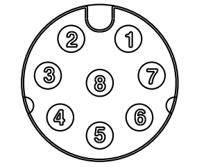
Ethernet pin out
The following reference can be used to fabricate suitable ethernet connector cables directly to the 8 pin circular connector.
| Circular connector Pin | RJ45 plug pin | Function |
|---|---|---|
| 3 | 8 | PoE+ |
| 2 | 7 | PoE+ |
| 8 | 6 | Rx- |
| 5 | 3 | Rx+ |
| 7 | 4 | PoE- |
| 1 | 5 | PoE- |
| 4 | 2 | Tx- |
| 6 | 1 | Tx+ |
Circular connector pin out 'looking into bulkhead mounted receptacle mounted on Mini'

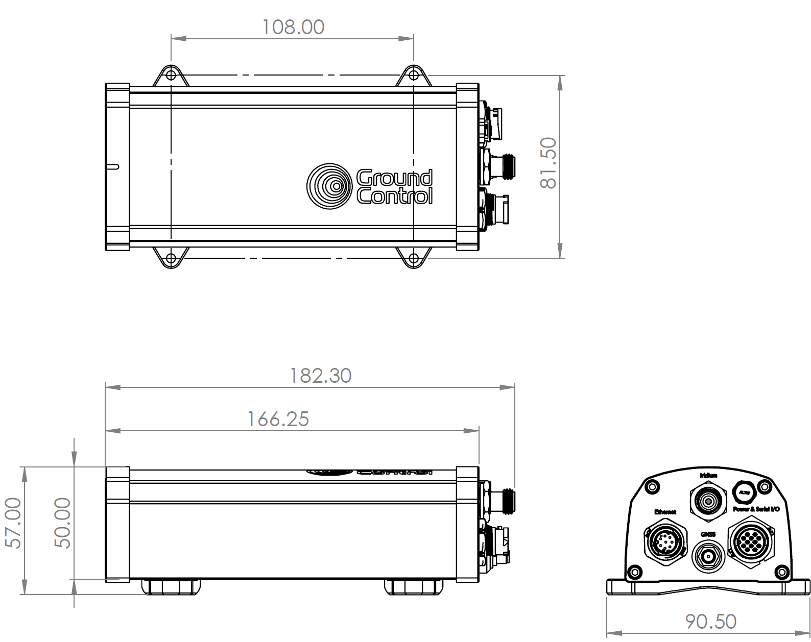
Dimensional drawing
Mounting hole(x4) diameter 4mm. Pan head screw recommended.

Downloads
Connectors and cable assemblies
Power and Serial IO 12-pin
| Connector | Manufacturer | Part Number |
|---|---|---|
| Bulkhead connector | Amphenol LTW | BU-12PMMP-LC7001 |
| Cable plug connector | Amphenol LTW | BU-12BFFA-LL7001 |
| Cable assembly - 2m length | Amphenol LTW | BU-12BFFM-LL7A02 |
Ethernet 8-pin
| Connector | Manufacturer | Part Number |
|---|---|---|
| Bulkhead connector | Amphenol LTW | AU-08PMMP-QC800 1 |
| Cable plug connector | Amphenol LTW | AU-08BFFA-QL8AP0 |
| Plug protective cap | Amphenol LTW | CAP-WAAMQPC1 |
| Cable assembly - 2m length | Amphenol LTW | AB-AU08FL-UPBML-QH002 |
