📣 Firmware Update:
Firmware Version 1.13.1 is now released! Please follow the link here or update via Cloudloop Device Manager.
Serial Configuration
The RockREMOTE serial ports can be configured on the UI under the Serial section which is broken in sub-menu items for Port A and Port B.
Hardware capability
RockREMOTE:
The RockREMOTE has two serial ports, Port A and Port B. Port A is a RS232/RS4XX port, it can support RS232, RS4XX in half duplex and full duplex. Port B is a full RS232 port with RTS, CTS, DTR, DSR, DCD and RI modem lines.
RockREMOTE Rugged:
The RockREMOTE Rugged has serial Port A which provides the same RS232 or RS4XX in half duplex and full duplex functionality.
Port B is not accessible on RockREMOTE Rugged.
RockREMOTE Pinout
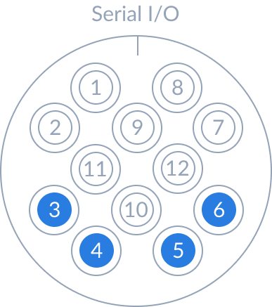
Port A
| Pin | RS4XX full duplex | RS4XX half duplex | RS232 |
|---|---|---|---|
| 1 | Ground | Ground | Ground |
| 2 | Ground | Ground | Ground |
| 3 | → TX (inverting) | ⇄ TX/RX (inverting) | → TX |
| 4 | → TX (non-inverting) | ⇄ TX/RX (non-inverting) | N/C |
| 5 | ← RX (non-inverting) | N/C | ← RX |
| 6 | ← RX (inverting) | N/C | N/C |
Port B
| Pin | Description | Pin | Description |
|---|---|---|---|
| 1 | Ground | 6 | ← CTS |
| 2 | Ground | 7 | → DTR |
| 3 | → TX | 8 | ← DCD |
| 4 | ← RX | 9 | ← DSR |
| 5 | → RTS | 10 | ← RI |
When using hardware flow control on PortB, RTS, CTS, DSR and DTR must be connected. Should the device not have DTR and DSR they should be looped together on PortB when wiring up the device. The same solution can be used by lopping together RTS and CTS if they're not used but DTR and DSR are used.
RockREMOTE Rugged Pinout

| Pin | Colour | Signal | RS4XX full duplex | RS4XX half duplex | RS232 | USB variant |
|---|---|---|---|---|---|---|
| 1 | Brown | Output 1 | Output 1 | |||
| 2 | Blue | Output 2 | Output 2 | |||
| 3 | White | ← RX (non-inverting) | ← Rx | Reserved | ||
| 4 | Green | ← RX (inverting) | USB+ | |||
| 5 | Yellow | → TX (non-inverting) | TX/RX (non-inverting) | USB- | ||
| 6 | Gray | → TX (inverting) | TX/RX (inverting) | → Tx | Reserved | |
| 7 | Pink | Input 2 | Input 2 | |||
| 8 | Red | Input 1 | Input 1 | |||
| 9 | Black | Reserved | USB +5V | |||
| 10 | Orange | Sleep | Sleep | |||
| 11 | Purple | Ground | Ground | |||
| 12 | Light Green | Reserved | Reserved |
Serial IO colour-coding is based on the optional 12pin cable accessory.
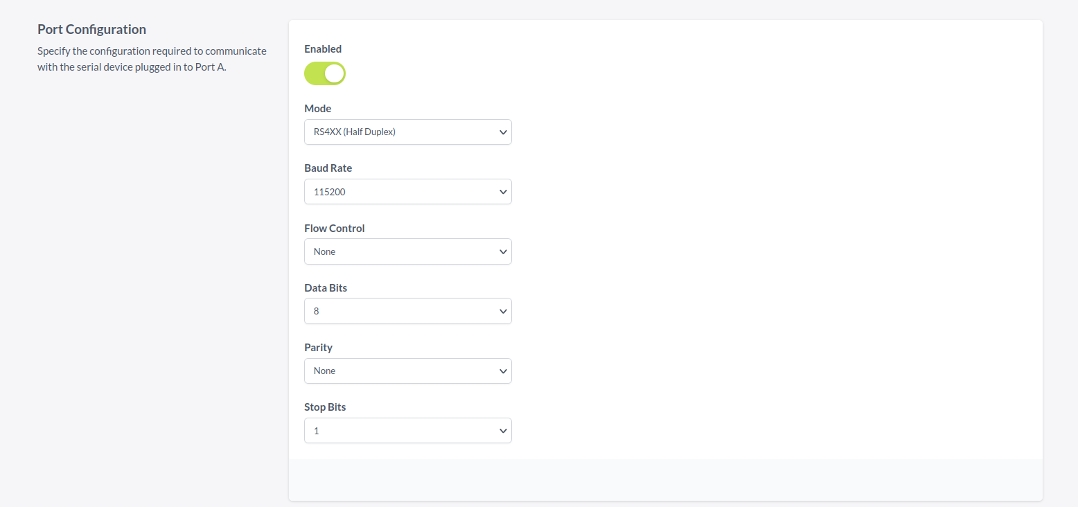
Port Configuration

Mode
| Modes | Port A | Port B |
|---|---|---|
| RS232 | ✔️ | ✔️ |
| RS4XX Half Duplex | ✔️ | ❌ |
| RS4XX Full Duplex | ✔️ | ❌ |
Baud Rate
Each port supports rates from 4800 bps to 921600 bps.
Flow Control
| Flow Control | Port A | Port B |
|---|---|---|
| No Flow Control | ✔️ | ✔️ |
| Software Flow Control | ✔️ | ✔️ |
| Hardware Flow Control | ❌ | ✔️ |
Data Bits
Each port supports 7 and 8 bit characters sizes.
Parity
Each port supports None, Space, Mark, Odd, and Even parity bit checking.
Stop Bits
Each port supports 1 and 2 stop bit(s).
Application Mode

GNSS NMEA
In this mode the GNSS NMEA output from the cellular module is transmitted from onto the serial port at the configured port configuration. It will output the following sentences:
- GGA - Global Positioning System Fix Data
- GLL - Geographical Position - Latitude/Longitude
- GSA - GPS DOP and Active Satellites
- GSV - GPS Satellites in View
- RMC - Recommended Minimum Specific GPS Data
- VTG - Course Over Ground and Ground Speed
This mode will works well in GNSS continuous mode which can be configured in the GNSS section.
Client Mode (TCP)
These options only appear when client mode is enabled.
In client mode the RockREMOTE will connect to a destination IPv4 and Port when serial data is ready to send, the connection timeout is configurable with the Connection Timeout. The connection will stay open for a number seconds to allow the destination to reply with data, this is configured by the Connection Idle Timeout.

Server Mode (TCP)
These options only appear when server mode is enabled.
In server mode the RockREMOTE will listen on port for a connection. The listen interface is enabled on the LAN interfaces by default but can be enabled on the WAN interfaces as well by enabling "Allow WAN Access", when this is enabled a list of allowed IPs should configured. This is configured as a IPv4 and a subnet mask using the CIDR notation.

Transmission Settings
These options only appear when server or client mode is enabled.
- Idle Timeout. The time in milliseconds the RockREMOTE will wait for additional data on the serial bus before sending the buffer.
- Buffer Size. Maximum number of bytes to store before the data is sent.
- End of line character. Send the chunk each time the end of line character is reached. Optional. This is configured as escaped ASCII characters and
\xprefix can be used to enter a hexadecimal byte.
All 3 transmission settings can be used together to dictate how often the RockREMOTE will send serial data. If the End of line characters have been configured then once these bytes have been observed that serial data is sent over the configured Routing Mode. If the End of line characters are not configured or not received the idle timeout or buffer size will determine how frequent the RockREMOTE will send serial data. It is possible to send bulk data by clearing End of Line characters and configuring a long idle timeout with a buffer size of the desired bulk data size.

