Ports and Wiring Diagrams
Ports
There are three main ports on the back of the RockAIR and, optionally, 3 SMA connectors if you have the version with external antennae. From left to right on the back of the device, they are:
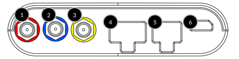
- Iridium external antenna (Red SMA connector)
- GPS external antenna (Blue SMA connector)
- Cellular external antenna (Yellow SMA connector)
- Switch/Alert input port (Molex)
- Power/Serial port (Molex)
- USB port for 5V power. (Pre V3 PCBA Micro USB, V3 PCBA USB-C)
Wiring
The RockAIR has two ports located on the rear of the device.
Switch/Alert Inputs
The 6 pin Molex connector provides up to 5 switch/alert inputs. By pulling any of pins 1-5 to ground (pin 6), the tracker will immediately transmit an alert. A secondary alert will be sent when the connection is open again.
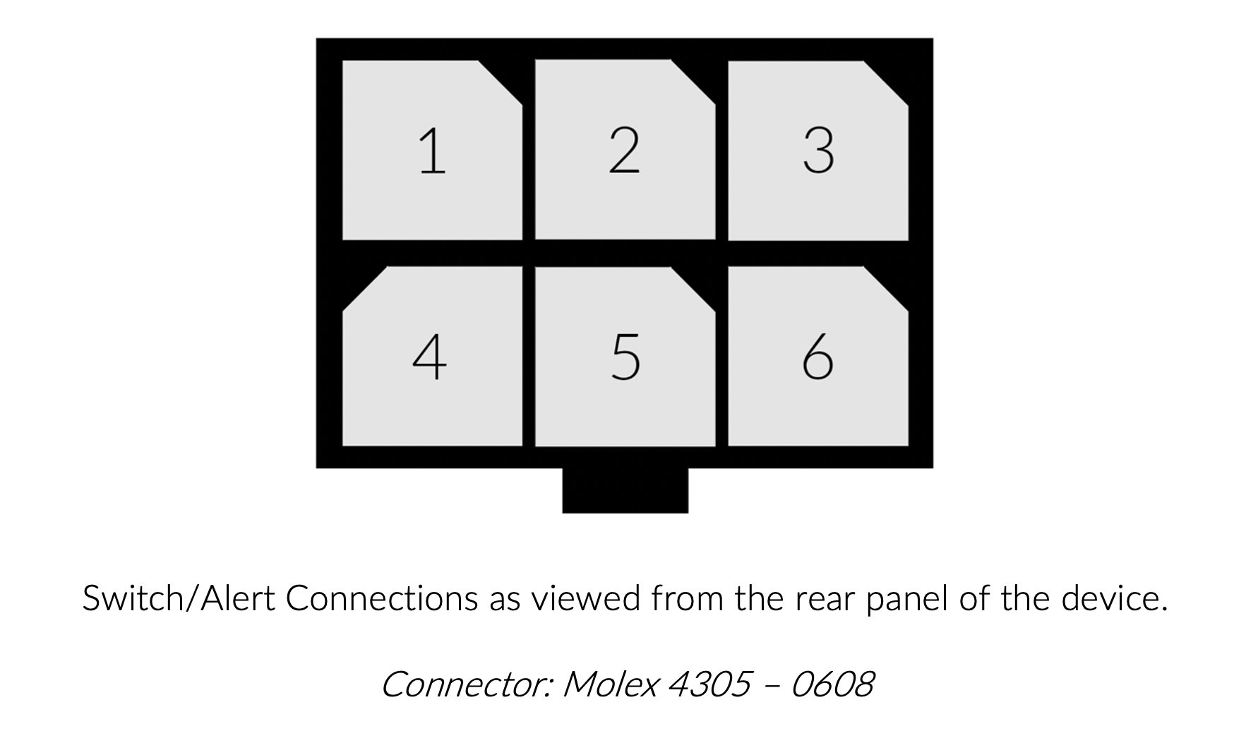
| Pin # | Serial | CORE and API | Colour |
|---|---|---|---|
| 1 | On_4 / Off_4 | Switch E (Falling / Rising) | Black |
| 2 | On_2 / Off_2 | Switch C (Falling / Rising) | Brown |
| 3 | On_0 / Off_0 | Switch A (Falling / Rising) | Red |
| 4 | On_3 / Off_3 | Switch D (Falling / Rising) | Orange |
| 5 | On_1 / Off_1 | Switch B (Falling / Rising) | Yellow |
| 6 | N/A (Ground) | N/A (Ground) | Green |
Switch inputs may be grounded via the common ground on a vehicle.
However, Pin 6 must NOT be connected to the vehicle’s common ground, as it is reserved exclusively as the tracker’s internal ground reference for switch inputs.
DC Power and Serial Connection
The 4 pin Molex connector provides 8-32vDC power and an RS232 Serial Interface driven by the popular MAX3232 IC which accepts an input of -25v to +25v.
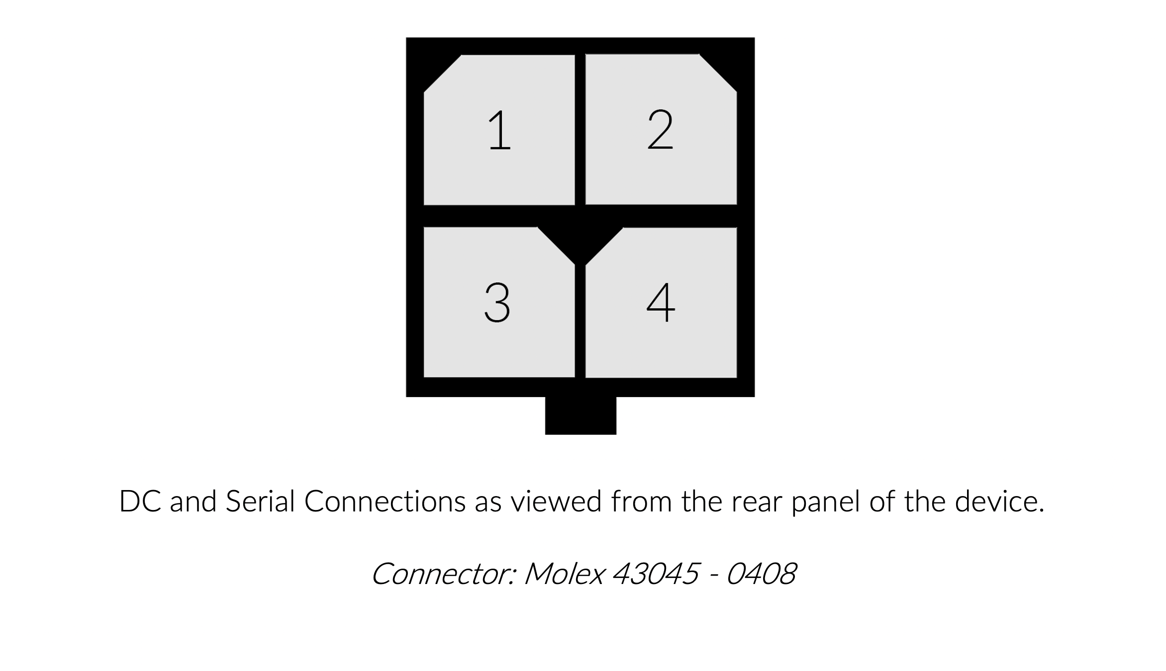
| Pin | Purpose | Colour (before Autumn 2020) | Colour (after Autumn 2020) |
|---|---|---|---|
| 1 | +ve 8-32vDC | Red | Red |
| 2 | -ve (Ground) | Black | Black |
| 3 | RS232 TX | Green | White |
| 4 | RS232 RX | Blue | Green |
When wiring the 4-pin Molex connector, ensure that your external DC power supply is connected only to Pin 1 (+ve 8–32 V DC) and Pin 2 (Ground).
Accidentally applying external DC voltage to the serial pins (Pin 3 RS232-TX or Pin 4 RS232-RX) can instantly destroy the onboard MAX3232 IC and disable the serial interface.